Robotics & RC
Grippers · sensor mounts · motor brackets
Parts that hold alignment, connect to hardware and keep your project moving.

For the people who make things
Not just the right shape.
The right part for the job.
We excel at making complex 3D shapes that are too difficult to CNC or injection mold, and that have to carry real-world loads.
Let's make it workFrom fits to functions
A successful test fit doesn't tell you how a part will behave under load, heat or repeated use. The numbers below are why.
| How the part is made | Typical strength | Tooling cost |
|---|---|---|
| 3D printed | ~15–30% of molded — weakest across the layers | None |
| Injection molded | 100% — strong in every direction | Tens of thousands of dollars |
| Forged carbon (our process) | Molded-class strength — no weak direction | Printed mold — a fraction of cut tooling |
Rough planning figures, not test data. Your part will vary — the pattern won't.
The full breakdown — why printed parts are weaker, and where forging closes the gapIndependent bend test
EasyComposites ran the same bend test on five materials and published the charts. Forged carbon carried more load than aluminum before it broke — and the optimized version carried the most of anything tested. The 3D printed samples in the same test never got close.
| Material | Peak load in the bend test | How it behaved |
|---|---|---|
| Optimized forged carbon | ~350 kg — highest of all five | Carried well past aluminum before failing. |
| Forged carbon | ~230 kg | More than aluminum — then broke suddenly, as carbon does. |
| Aluminum | ~175 kg | Didn't break — it bent and kept carrying load to the end of the test. |
| Markforged (3D printed) | ~100 kg | Broke early, at roughly half the load aluminum carried. |
| Onyx (3D printed) | ~40 kg | Lowest of all — failed long before the others. |
Figures are read from EasyComposites' published bend-test charts — approximations for their tested specimens, not universal material-strength ratings. Your part will vary with geometry, fiber content and loading. Source: EasyComposites' mechanical properties investigation.
Why the printed samples lose
A 3D printed part is built layer on layer. The bond between layers is the weak point — load that runs across the layers pulls them apart, so the part fails at a fraction of what the material itself can do. That's why the printed samples broke early no matter how good the material sounds on a datasheet.
Forged carbon has no layers. Chopped fiber is compressed into the mold under heat, so it carries load in every direction — which is how it reaches aluminum-class strength without aluminum's weight.
See the full strength breakdownStraight from the shop
We excel at making complex 3D shapes that are too difficult to CNC or injection mold, and that have to carry real-world loads. Every part shown is forged carbon; what differs is surface finish. Unpolished parts show the print lines. Polished parts reveal the carbon fiber underneath.

Forged around a disc brake caliper, brass bushings and anodized hub inserts.

Shown with the brake hardware the arm was designed around. Part weight 230 g including metal inserts.

One forged form — the print lines stay visible unpolished.

Polished so the carbon fiber shows through. Pictured on the assembly fixtures.

Forged around the rod ends and springs they carry.

Bores and seats formed in the forging itself.

Four mounts carrying a single steel shaft.

The kind of complex geometry that is expensive and difficult to machine in aluminum.
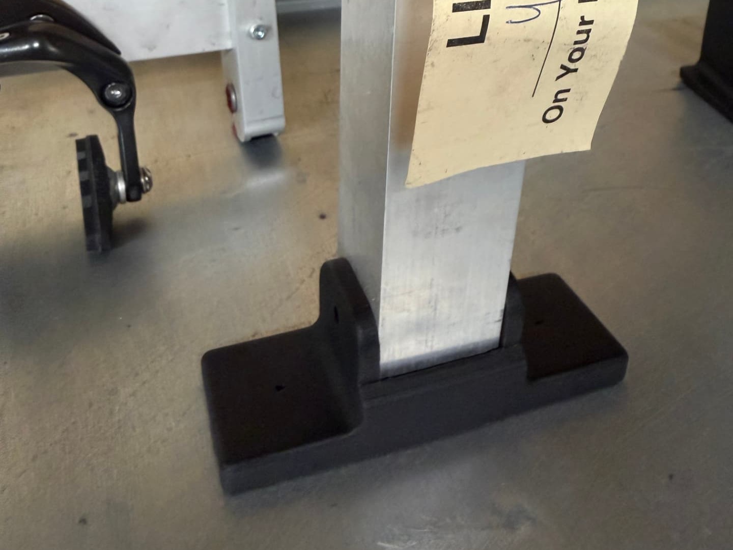
Fitted to the frame extrusion, ready to pack. This bracket carries 200 lb of real-world force — a lighter and cheaper alternative to aluminum.

Another block from the same run.
Real parts from recent e-cycle work — not renders. Finish level is a choice: polished, or left with the print lines.
Put your design to work
Grippers · sensor mounts · motor brackets
Parts that hold alignment, connect to hardware and keep your project moving.
Jigs · clamps · adapters · replacement knobs
Custom geometry for the machine, tool or awkward space you already have.
Cable guides · equipment mounts · custom holders
A better fit for your setup, with connections and repeated handling considered.
Example applications. Pictured parts are illustrative.
More than an infill setting
Review where it bends, where it carries force, and where ribs or thicker walls could help.
Match material to stiffness, impact, temperature and the conditions the part will see.
Consider layer adhesion, wall layout and orientation around the working loads.
Plan threaded inserts, mating surfaces and the checks needed for your application.
Start with your model, what the part does and what isn't working in the current print.
Consider loads, temperatures, tolerances and connections before choosing a printing approach.
Agree the material and design, then define finishing and checks around the intended use.
Before you send the file
Typical figures for this kind of work. Your part decides the real numbers.
Common starting points are PETG, ASA, nylon (PA12) and glass- or carbon-filled nylons. Heat-resistant options include PC and PEEK-class materials; TPU covers flexible sections. Material gets chosen against stiffness, impact, temperature and the environment your part actually works in—not by default.
Typically around ±0.2 mm on features under 100 mm and roughly ±0.5 mm across a 300 mm part, depending on process and material. Where a dimension really matters—a bore, a mating face, an insert seat—mark it on the drawing and we plan the print and finishing around it. Critical bores can be reamed or machined after printing.
Most single parts and small batches are back in roughly 5–9 days from an agreed design, including the review, print, finishing and checks. Larger runs, post-machining or secondary operations add time—we confirm the date before starting, not after.
Against the drawing or model you sent: overall dimensions, the features you marked critical, fastener and insert fit, and the mating surface. We also look for print defects that affect function—incomplete walls, delamination, porosity. If your part has a defined job, we agree a functional check with you: a load, a fit test, a cycle count. You get the results with the part.
A STEP or STL is best. A printed sample, photos of it in place and the parts it mates with are often enough to start. Tell us which dimensions you cannot change.
We tell you before printing. Wall thickness, print direction and details that fail under load are the usual ones—we propose changes and agree them with you before anything is made.
Tell us what your part needs to do—not just what it looks like.